
What is an Inert Gas or IG System on Ships?
Oil tankers carry oil of different grades and quality, having property to produce flammable vapors and gases when loaded for transportation. Even with no cargo on board, there can be harmful flammable gases present in the hold. When the vapor produced by an oil cargo is mixed with certain concentration of air primarily containing oxygen, it can result in explosion which results in damages to the property, marine pollution and loss of life
For safety against such explosion, Inert gas system is used on board. It can be through as a separate inert gas plant or flue gas produced by ship’s boiler.
What is Inert gas and Inert gas system?
Inert gas system is the most important integrated system for oil tankers for safe operation of the ship.
Inert gas is the gas which contains insufficient oxygen (normally less then 8 %) to suppress combustion of flammable hydrocarbon gases.
Inert gas system spreads the inert gas over the oil cargo hydrocarbon mixture which increases the lower explosion limit LEL (lower concentration at which the vapors can be ignited), simultaneously decreasing the Higher explosion limit HEL (Higher concentration at which vapor explodes). When the concentration reaches around 10 %, an atmosphere is created inside tank in which hydrocarbon vapors cannot burn. The concentration of inert gas is kept around 5% as a safety limit.
Components and description of IG system:
The following components are used in a typical inert gas system in oil tankers:
1) Exhaust gases source: inert gas source is taken from exhaust uptakes of boiler or main engine as contains flue gases in it.
2) Inert gas isolating valve: It serve as the supply valve from uptake to the rest of the system isolating both the systems when not in use.
3) Scrubbing tower: Flue gas enters the scrub tower from bottom and passes through a series of water spray and baffle plates to cool, clean and moist the gases. The SO2 level decreases up to 90% and gas becomes clear of soot.
4) Demister: Normally made of polypropylene, it is used to absorb moisture and water from the treated flue gas.
5) Gas Blower: Normally two types of fan blowers are used, a steam driven turbine blower for I.G operation and an electrically driven blower for topping up purpose.
6) I.G pressure regulating valve: The pressure within the tanks varies with the property of oil and atmospheric condition. To control this variation and to avoid overheating of blower fan, a pressure regulator valve is attached after blower discharge which re-circulates the excess gas back to scrubbing tower.
7) Deck seal: Purpose of the deck seal is to stop the gases to return back which are coming from the blower to cargo tanks. Normally wet type deck seals are used. A demister is fitted to absorb the moisture carried away by the gases.
8) Mechanical non return valve: It is an additional non return mechanical device inline with deck seal.
9) Deck isolating valve: The engine room system can be isolated fully with the deck system with the help of this valve.
10) Pressure Vacuum (PV) breaker: The PV breaker helps in controlling the over or under pressurization of cargo tanks. The PV breaker vent is fitted with flame trap to avoid fire to ignite when loading or discharging operation is going on when in port.
11) Cargo tank isolating valves: A vessel has numbers of cargo holds and each hold is provided with an isolating valve. The valve controls the flow of inert gas to hold and is operated only by a responsible officer in the vessel.
12) Mast riser: Mast riser is used to maintain a positive pressure of inert gas at the time of loading of cargo and during the loading time it is kept open to avoid pressurization of cargo tank.
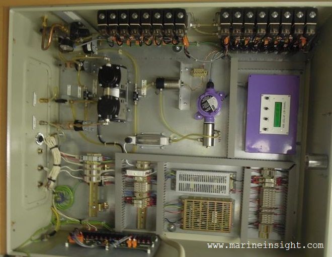
Safety and alarm system: The Inert gas plant is provided with various safety features to safeguard the tank and its own machinery.
Following are various alarms (with Shutdown) incorporated in the Inert Gas plant on board ship:
- High Level in scrubber leads to alarm and shutdown of blower and scrubber tower
- Low pressure sea water supply (approx. 0.7 bar) to scrubber tower leads to alarm and shutdown of blower
- Low pressure sea water supply (approx. 1.5 bar) to deck seal leads to alarm and shutdown of blower
- High inert gas temperature (approx. 70 deg C) leads to alarm and shutdown of blower
- Low pressure in line after blower (approx. 250mm wg) leads to alarm and shutdown of blower
- Oxygen content high (8%) leads to alarm and shutdown of gas delivery to deck
- Low level in deck seal leads to alarm and shutdown of gas delivery to deck
- Power failure leads to alarm and shutdown of blower and scrubber tower
- Emergency stop leads to alarm and shutdown of blower and scrubber tower
Following are various alarms incorporated in the Inert Gas plant:
- Scrubber low level
- Deck seal High level
- Low O2 Content (1%)
- High O2 Content (5%)
- Low lube oil pressure alarm
Working of Inert Gas Plant:

Image for representation purpose only. All rights reserved.
The basis of inert gas production in the IG plant is the flue gas generated from the ship’s boiler. The high temperature gas mixture from the boiler uptake is treated in an inert gas plant which cleans, cools and supplies the inert gas to the individual tanks via PV valves and breakers to ensure safety of tank structure and atmosphere.
The system can be divided in to two basic groups:
a) A production plant to produce inert gas and deliver it under pressure, by means of blower(s), to the cargo tanks.
b) A distribution system to control the passage of inert gas into the appropriate cargo tanks at the required time.
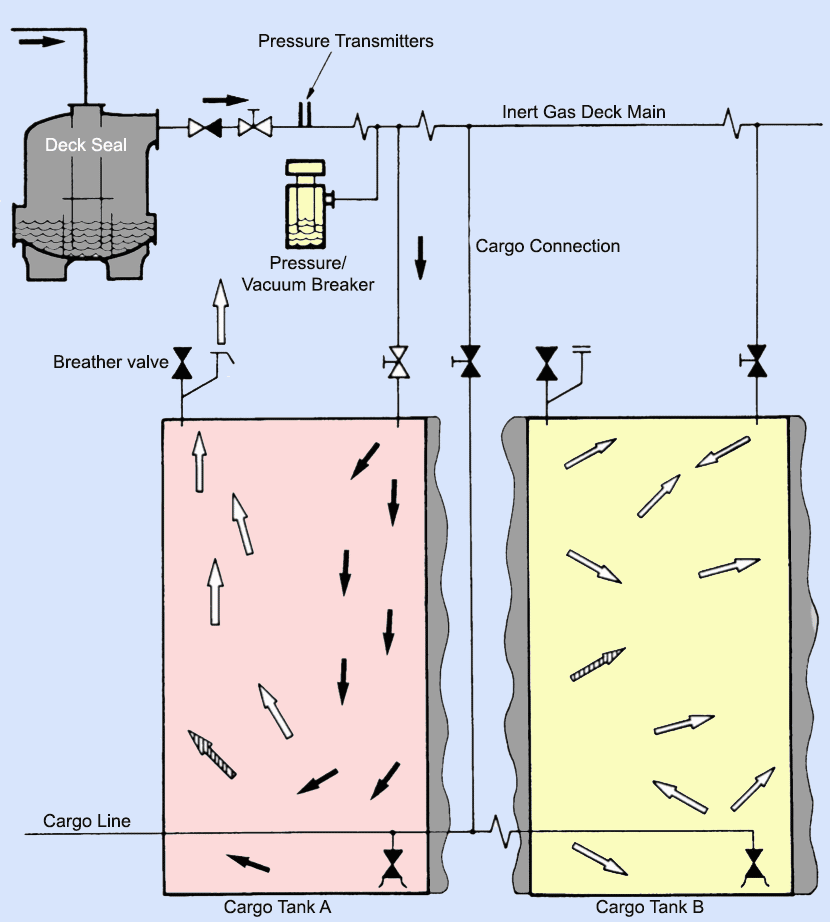
Image for representation purpose only. All rights reserved.
Brief working procedure:
- Boiler uptake gases are drawn to the scrubber unit via flue gas isolating valve(s) to the scrubber unit.
- In the scrubber unit the gas is cooled, cleaned and dried before being supplied in to the tanks.
- Motor driven inert gas blowers supplies the treated gas from scrubber tower to the tanks through . They are mounted on rubber vibration absorbers and isolated from the piping by rubber expansion bellows.
- Regulation of gas quantity delivered to deck is taken care of by the gas control valves and the deck pressure is managed by pressure controller. If the deck pressure is lower than the set point the output signal will be raised to open the valve more, and vice versa if the deck pressure is lower than the set-point. These valves will then work in cooperation to keep both the deck pressure / blower pressure at their respective set point without starving or overfeeding the circuit.
- Before entering the deck line, the gas passes through the deck water seal which also acts as non-return valve automatically preventing the back-flow of explosive gases from the cargo tanks.
- After the deck seal the inert gas relief is mounted to balance built-up deck water seal pressure when the system is shut down. In case of a failure of both the deck seal and the non-return valve, the relief valve will vent the gases flowing from the cargo tank into the atmosphere
- The oxygen analyser which is fitted after the blower separates the “production” and “distribution” components of the plant and analyzes the oxygen content of the gas and if it is more than 8%, it alarms and shut downs the plant
marineinsight